RNZ
RADIO CORPORATION OF NEW ZEALAND LTD
80 Courtenay Place, WELLINGTON, C3
GPO Box 1365
Telegrams: "RADICENTRE" …………. Service Bulletin No. 82
Telephone 55-020 …………………….. Date: 1 November 1944
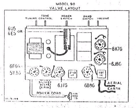
MODEL 90
7 Valve Band Spread Receiver
 SENSITIVITY TESTS
Volume Control full on, Tone Control position 5.
Sensitivity Tests: (Microvolts input to give standard output of 50 milliwatts)
|
Frequency |
Input to: |
Microvolts |
|
455 Kc. |
Grid 6B8 |
5,000 |
|
455 Kc. |
Grid 6J8 |
80 |
|
1400 Kc. |
Antenna lead through dummy antenna |
2.5 |
|
1000 Kc. |
Antenna lead through dummy antenna |
3.0 |
|
600 Kc. |
Antenna lead through dummy antenna |
4.0 |
|
15 Mc. |
Antenna lead through dummy antenna |
1.5 |
|
6 Mc. |
Antenna lead through dummy antenna |
1.5 |
|
Bandspread |
Antenna lead through dummy antenna |
1.5 |
RADIO CORPORATION OF NEW ZEALAND LIMITED
ALIGNMENT PROCEDURE MODEL 90.
1. EQUIPMENT.
The following equipment is necessary in order to carry out the alignment of the Model 90 Bandspread Receiver :-
(a) Signal Generator complete with Dummy Antenna.
(b) Standard Frequency Oscillator, operating on 100 k.c. and 1000 K.c.
(c) Output Meter.
2. ALIGNMENT OF INTERMEDIATE FREQUENCY CHANNEL.
Set volume control to maximum position and tone control to position 7.
Set bandswitch to broadcast position. Connect output meter across primary of the output transformer.
Connect signal generator to grid of 6B8 through a .05 ufd blocking condenser.
Set signal generator to 455 k.c. and adjust second I.F. transformer trimmers for maximum output, keeping signal generator to a level which will not give more than 50 milliwatts output from the receiver (i.e. 15.8 volts across 5000 ohm output transformer). Now change signal generator output lead to the grid of the 6K8 and adjust the first I.F. transformer trimmers to give maximum output. The input to the first Intermediate Frequency stage to give a standard output of 50 milliwatts, should be 80 Microvolts.
3. ALIGNMENT OF BROADCAST BAND.
Connect signal generator through Dummy Antenna to the Antenna and earth leads of the receiver. Set signal generator and receiver to 1400 K.c. and adjust broadcast oscillator trimmer until signal is heard. Adjust Antenna and R.F. trimmers for maximum output. Set signal generator to 600 K.c, and tune in signal on receiver. Adjust broadcast padder while rocking tuning condenser to give maximum output. Now check alignment at 1400 K.c. as previously, and then again at 600 K.c.
4. ALIGNMENT OP SHORTWAVE BANDS.
4 (1) 6-18 M.c. Full Coverage Band.
Set signal generator and receiver to 18 M.c. and switch Bandswitch to 6 - 18 M.c. S.W. Band. Tune in Signal with shortwave oscillator trimmer making sure that this circuit is not tuned to the image frequency, (i.e. adjust this trimmer to the peak which gives minimum trimmer capacity). Adjust Short Wave Antenna and R.F. trimmers to give maximum output. (If two positions are noted on antenna and R.F. trimmers adjust to maximum capacity position). On Short Wave this receiver has a fixed padder and if alignment is...?
Columbus Model 90
MODEL 90 -7 VALVE RECEIVER WITH CALIBRATED SHORT-WAVE BAND
EXPANSION AND ELEVEN POINT TONE CONTROL
This is a 7 valve five-band receiver incorporating calibrated short-wave band expansion. The sensitivity on both broadcast and short-wave bands is of such a high order that any increase would be of no practical value in the average location. The frequency ranges, are as follows ;-
Broadcast band:-
550 - 1600 k.c.
High frequency bands:-
6 - 18 m/c, 14,850 - 15,750 k.c, 11,650 – 12,100 k.c., 9,450 - 9,750 k.c.
Thus the principal international shortwave bands are fully covered, the three most popular having the tuning expanded by approximately 25 times by means of bandspread. This results in the same ease of tuning on short-wave as on the broadcast band and produces an entirely new conception of short-wave listening.
In order to maintain absolute constancy of calibration silvered-mica fixed condensers, and high quality trimmers are used in the oscillator circuits and the receiver is also exactly compensated against changes in temperature. By means of a special arrangement the oscillator frequency is maintained consistent irrespective of changes in A.V.C. voltage. This greatly reduces the effects of fading. A "magic-eye" is incorporated to ensure ease of accurate tuning.
The valves used are as follows:-
6K7 - R.F. Amplifier
6J8 - Converter
6B8 - I.F. Amplifier, Detector Amplifier and A.V.C.
6J7 - Audio Amplifier
6F6 - Output pentode
6U5 - Tuning Indicator
5Y3 - Rectifier
1-3 Eleven Point Tone Control
An important feature of the Model 90 is the wide control of tone obtainable with the 11 position switch. The variety of tones obtained at the different positions are as follows:-
|
1) |
Approx 10% feedback |
Tops cut severely |
Bass normal |
|
2) |
Approx 10% feedback |
Tops cut severely |
Bass normal |
|
3) |
Approx 10% feedback |
Tops cut still ;less |
Bass normal |
|
4) |
Approx 10% feedback |
Slight top cut |
Bass normal |
|
5) |
Approx 10% feedback |
No top cut |
Bass normal |
|
6) |
Approx 25% feedback |
Top boost |
Bass Boost |
|
7) |
Approx 25% feedback |
Slight top boost |
Less bass boost |
|
8) |
Approx 25% feedback |
No top boost |
No bass boost |
|
9) |
Approx 25% feedback |
Increasing top cut |
No bass boost |
|
10) |
Approx 25% feedback |
Increasing top cut |
No bass boost |
|
11) |
Approx 25% feedback |
Increasing top cut |
No bass boost |
-2-
It will be seen from this that the positions one to five are for distant stations or any stations where the full sensitivity of the receiver is required. For local stations the positions 6 to 11 give a wide control of tone with the added advantage of considerably more inverse feed back. Positions 6, 7 & 8 give excellent frequency response characteristics, particularly position 6 where there is top boost which compensates for loss of tops due to the tuned circuits of the I.F.T's etc The bass being boosted at the same time makes it possible to operate the receiver at a very low volume level and still maintain an even response level for all frequencies.
Note. If it is desired, to bring the tops up for position 7, so they are actually between that for 6 and 8, a 0.15 mfd condenser should be fitted between the junction of the 500 ohm resistor and contact 7 of the switch and ground.
2-1. I.F. Alignment.
The characteristics of I.F. transformers are such that, if they are aligned for maximum response using a normal amplitude-modulated signal generator or oscillator, the resonance curve will resemble closely the flat-top shape. An approximate idea of the shape of the curve may be obtained by swinging the signal generator frequency across 455 k.c. and noting the change in output after lining up in the usual way. It will generally be found that by screwing out the primary (plate circuit) trimmer in the first I.F. transformer (only) a fraction of a turn until the output voltage drops approximately 10 per cent, the correct resonance curve will be obtained.
The load from the signal generator to the grid of the 6J8 tube should not provide a D.C. path to chassis, as this will remove the bias from the tube.
A condenser should be inserted in the lead, if necessary, and the normal grid-cap should be left on the tube. This condenser is incorporated in the R.N.Z. All Wave Dummy Antenna.
2-2. B/C Band Alignment.
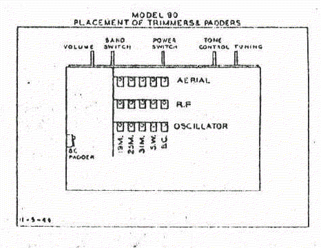
Connect aerial and earth leads to signal generator through standard all wave dummy antenna and connect output meter in circuit across speaker transformer. Set dial-pointer so that centre of pointer is directly behind centre of line marking end of scale when gang plates are fully meshed. The location of trimmers under the chassis is shown separately on page 4.
Set signal generator frequency at 1400 k.c. and tune receiver to 1400 k.c. on dial scale. Tune in signal by adjusting B.C. oscillator trimmer. Trimmer adjustments may be made, if desired, without removing the chassis from the cabinet, as slots are provided in the base for this purpose. Adjust B/C, R.F. and aerial trimmer for maximum output. Set signal generator at 600 k.c. and tune-in signal. .Rock gang and adjust padder for maximum output. If the padder setting is found to need appreciable alteration it will be necessary to repeat the previous adjustments at 1400 k.c. Calibration may then be checked by noting the positions of B/C stations on the dial or by switching on the 100 k.c. oscillator in the Frequency Standard SFl and noting that the 100 k.c. points fall correctly on the dial.
-3-
The model SFI consists of a temperature-compensated oscillator, with built-in power supply, which is capable of being set accurately to 570, 100 or 1,000 k.c.
The harmonics of this oscillator fall at convenient points in the S/W bands covered by Model 90, and are used for calibration and alignment.
Before using the Frequency Standard it is essential that its frequency be sat accurately. To do this, tune in Station 2YA on the receiver under test and switch on the Frequency Standard. After allowing 10 minutes for the initial warming-up of the oscillator valve in the Frequency Standard, adjust the 570 k.c. trimmer knob on the front panel until the note which is heard is reduced to zero beat. The frequency is, by this means, adjusted to 570 k.c., and the harmonics will then serve as accurate frequency standards for alignment of the S/W Bands.
Switch the Signal Generator to the "6 m/c -18 m/c" band and align at 16 m/c, ensuring that the calibration is accurate, as an adjustment to the oscillator trimmer of this band after the spread bands have been adjusted will throw all the spread bands off calibration. Now tune to 11,400 k. c. in the "6-18 m/c" band where a harmonic of the 570 k. c. signal from the S.F.I, should be heard. Leaving the receiver for a moment, the S.F.I., is switched to the 100 k.c. position and the appropriate control varied until the loudest repeat spot, or signal, is heard. Leaving the S.F.I. set, the receiver is tuned from 11,400 k, c. to 12,000 k. c. by counting the repeat spots. 12,000 k.c. should fall on the sixth repeat point excluding the point at 11,400 k.c. Now leave the receiver and switch the S.F.I, to the 1000 k.c. position, adjusting the appropriate control until the signal is heard. This calibration of the S.F.I. may be checked by switching the receiver to B.C. when the 100 k.c. repeat points should be heard at every 100 k.c. on the band, the 1000 k.c. repeat points at every 1000 k.c. on the band.
When aligning the spread bands, the 19 meter band must be aligned first. Switch on the 570 k.c. oscillator in S.F.I. and note the point in the 19 meter band at which a signal is received. This should be 15,390 k.c. If too high an output from the Frequency Standard is used, weaker signals, which are images of other harmonics, will be received at other points on the dial, so the output from the S.F.I. should be reduced if these images prove confusing. Due to the difficulty in accurately setting the normal signal generator or oscillator it is necessary to use the S.F.I. to set the receiver oscillator frequency correctly.
The oscillator trimmer should be adjusted, to bring the 15,390 k.c. signal to its correct point on the dial. The Frequency Standard may then be switched to 1000 k.c. and the calibration checked at 15,000 k.c. Finally switch to 100 k.c. and note that a signal appears at each 100 k.c. point on the dial. Now set dial at 15,000 k.c, and adjust the signal generator until a signal is heard. Adjust the 19 meter R.F. and aerial trimmers for maximum output. If there is any slight discrepancy in the amount of band spread, the oscillator trimmer should be adjusted so that the calibration is correct within the recognised international S/W bands, which are :-
15,000 …. 15,350 k.c., 11,700…. 12,000 k.c., 9,500…. 9,700 k.c.
-4-
If the signals are received at two points when adjusting the oscillator trimmer, the correct adjustment is that with the trimmer screwed furtherest out. Similarly, if two peaks are noted when adjusting the R.F. and aerial trimmers, the correct sitting is that with these trimmer screwed furtherest in.
Now switch in turn the 25 and 31 meter bands and repeat the above procedure. The actual alignment of R.F. and aerial trimmers should be done at approximately the centre of the scale, that is, 15,200, 11,700 and 9,600 k.c.
By utilising the Frequency Standard in conjunction with the receiver it will be possible to obtain approximate dial settings for the signal generator for these frequencies. However, the 570 k.c. oscillator in the Frequency Standard should always be used to fix the exact calibration on the receiver being tested. The points at which harmonics of the 570 k.c. oscillator fall are :-
17,670 k.c., 15,390 k.c., 11,400 k.c., 9,690 k.c., 18,240 k.c., 11,970 k.c.
5. GRAMOPHONE CONNECTION.
Owing to the limited demand for gramophone pick-up connections, it is not standard practice to incorporate such arrangements in this receiver.
Instructions covering the necessary modifications may be obtained on application to the factory and, if required, the additional parts, already wired for connection to the receiver, can be supplied at a nominal charge.